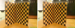
The left figures shown below represent these sets of inputs. In the first set, we took sample points from the top, bottom and middle (vertical) part of the checkerboard. In the second, we considered points from the leftmost, middle and rightmost parts. In the third, sample points were taken only from the center part of the board. In the last set, we took sample points from the top, bottom and middle (horizontal) part.

Figure 1: input sample points (left) and the output of the calibration (right)

Figure 2: input sample points (left) and the output of the calibration (right)

Figure 3: input sample points (left) and the output of the calibration (right)

Figure 4: input sample points (left) and the output of the calibration (right)
As we can see, the first and fourth sets produces the best calibrations for the camera. This is seen by the red crosshairs located at the corners of the checkerboards in the right figures. Using the second set of inputs causes the calibration to fail at the top and bottom parts of the grid. While upon using the third set, the calibration fails at the outer regions of the board. This is reasonable since we only got sample points from the center.
No comments:
Post a Comment