teamwork!!!
Friday, October 15, 2010
AP187 Act10: Video Processing
Tuesday, October 5, 2010
AP187 Act9: Stereometry


The focus of the camera is traditionally obtained by camera calibration like in Activity 8. However, for the camera that we've used the focus is already explicitly stated to be equal to 6.6cm.
Using the equation below, we can obtain the depth of the rubix cube based on the two images.
f is the focus of the camera
x2, x1 are corresponding points on the object from the two images
z is the depth of the said point
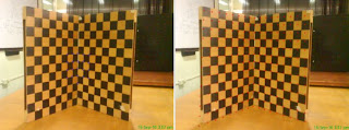
We now consider the edges of the rubix cube as the corresponding points that will be used to calculate the the depth z.
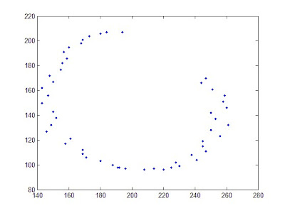
The figure above was obtained by plotting the the calculated depth and its corresponding x, y coordinates from either one of the two images. The figure indeed resembles the rubix cube. Credits to BA for letting us use his camera.
AP187 Act8: Camera Calibration
The left figures shown below represent these sets of inputs. In the first set, we took sample points from the top, bottom and middle (vertical) part of the checkerboard. In the second, we considered points from the leftmost, middle and rightmost parts. In the third, sample points were taken only from the center part of the board. In the last set, we took sample points from the top, bottom and middle (horizontal) part.


As we can see, the first and fourth sets produces the best calibrations for the camera. This is seen by the red crosshairs located at the corners of the checkerboards in the right figures. Using the second set of inputs causes the calibration to fail at the top and bottom parts of the grid. While upon using the third set, the calibration fails at the outer regions of the board. This is reasonable since we only got sample points from the center.
AP187 Act5: Measuring the Gamut of Color Displays and Prints
AP187 Act3: Familiarization with light-matter interaction
Figure 2: Objects demonstrating diffraction
Light may scatter when it interacts with matter. This scattering will be dependent on the wavelength of the incident light. So for certain materials, it will cause light to separate into different colors. Due to the wave nature of light when it reaches an aperture, light gets diffracted and casts a shadow shown in the picture.

Trichromaticity and addition and subtraction of color are demonstrated in these pictures.
Reflectances
Below are the reflectances from different colored objects.


Thursday, September 16, 2010
AP187 Act2: Familiarization with Properties of Light Sources
We gathered the following light sources: 2 cellphone LCDs, incandescent light, stove, flourescent and sunlight. The emittance spectra of the said light sources were then obtained using a spectroradiometer. Results are shown below.
Emittance Spectra of two Cellphones
Next, we computed for the emittance spectrum of a blackbody radiator for temperatures in the range. A video below shows how the emittance spectrum varies as the temperature increases. With this, we will be able to identify the color that an object will emit given its temperature.


